Design and prototyping a laser coating fixture
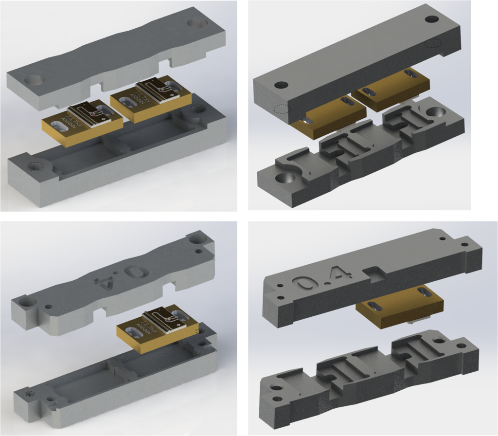
A process of coating a laser’s facet to modify the optical output requires a small fixture to hold the laser. This fixture serves to protect the laser from damage during the coating process as well as limit the surfaces that will be coated to only those that require coating. A previous fixture design (lower) had several design limitations; thin walls in several places (as thin as 0.5 mm) led to fixtures being bent, as well as low strength aluminum used as the fixture material. This legacy fixture design was easily damaged during the loading & unloading step and led to many lasers being damaged in the process.
A new fixture design was made to address these challenges, including the following;
- Increase wall thickness in key areas.
- Machine parts from a high strength material. The material had to be non-magnetic to avid steering the electron beam used in coating. Aluminum 7075 with a yield strength of 75 ksi was chosen.
- Simplify the fixture design to reduce cost.
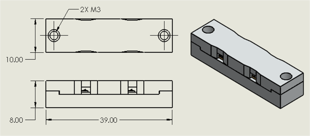
- Maintain the external dimensions of the fixture to ensure it still fits in other existing coating equipment.
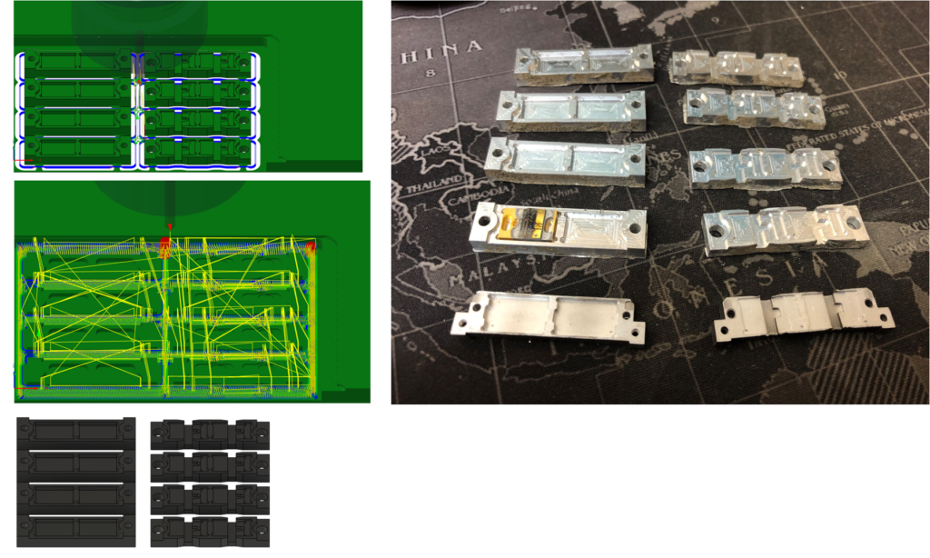
Advances in CNC machining and CAM have made machining easily accessible. The CAM set-up for a set of prototype parts was completed and parts were machined in under a few hours. The ability to design and prototype parts quickly enables engineers to test their designs and creativity in record time.
Design and prototyping of a laser interface fixture
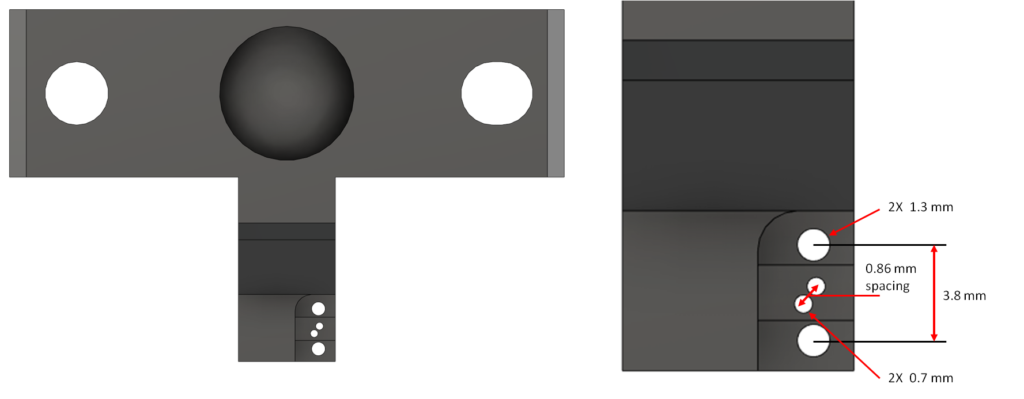
In order complete production testing of lasers, it is necessary interface with the laser diode and thermistor connection pads. These pads are quite small, with spacing between positive and negative laser diode pads of only 3.8 mm and only 0.86 mm between the thermistor pads. Spring loaded contacts, commonly called pogo pins, are used to make contact to the pads. The laser diode pins are 1.3 mm in diameter and the thermistor pins are 0.7 mm in diameter. A laser pin block (shown right) was modeled to accomplish this interface.
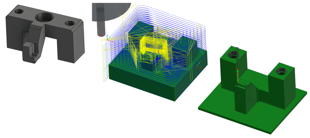
The part must not conduct electricity to avoid shorting across the pogo pins, so delrin was chosen as the material. The CAM set-up for this part was completed to enable the part to be quickly machined. This set-up called for drilling several delicate features in the part to accept the 0.7 mm and 1.3 mm pogo pins. To accomplish this, the part is first machined upside down to access the pogo pin bores and ensure the part has enough stiffness where needed. This allows 80% of the part features to be machined in this first orientation. A second operation was created to machine the remaining features on the top side of the part.
The finished design was a success and proved to have the tight positional placement needed to interface with the laser. This approach of rapidly designing and machining a part in-house led to multiple parts being completed in just a few hours time. When using a traditional machine shop, it is not uncommon to have lead times of 2-4 weeks t receive parts. By machining this design in-house, it was possible to shave those 2-4 weeks off the project timeline and deliver a working solution the same day.